A-A-52414B

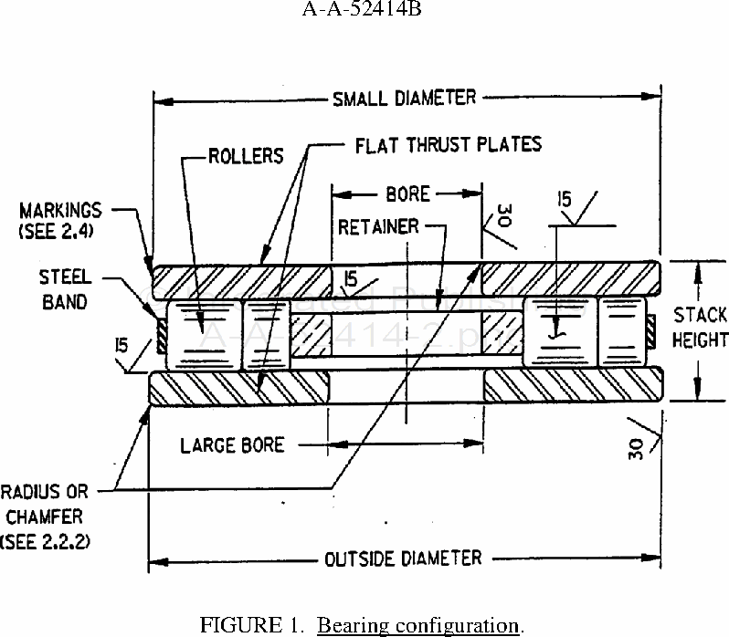
FIGURE 1. Bearing configuration.
2.2.1 Size. The size of the roller thrust bearings and tolerances shall be determined based on specific bearing application requirements and shall be given in the engineering drawing. Factors such as load, rpm, environmental conditions (e.g., temperature, humidity) are taken into consideration. The basic empirical formula used for the dynamic load capacity is explained in 6.2.
2.2.2 Radius or chamfer. Bearings must clear the maximum fillet radius of the mating shaft or housing. A radius or chamfer (see figure 1), of 0.031 inch minimum, shall be used on the bore and outer diameter.
2.3 Surfaces. The surfaces labeled 15 and 30 in figure 1 shall have a maximum surface roughness of 15 and 30 microinches, respectively. Ground surfaces shall be free from tool marks, chatter waves, pits, rust or other injurious defects. All other surfaces shall have a smooth machine finish, free from scale. The bearings shall be supplied without lubrication, but with a coating of rust preventive film.
2.4 Identification and markings. The product shall be identified and marked in accordance with the engineering drawing to include, as a minimum, the military part number and the manufacturer's CAGE code and part number (see 6.1).
For Parts Inquires submit RFQ to Parts Hangar, Inc.
© Copyright 2015 Integrated Publishing, Inc.
A Service Disabled Veteran Owned Small Business